Reading a Fender Bandmaster 5E7 Schematic

A buddy of mine posted this photo on Facebook — a printed schematic on a desk, two fingers pointing at parts of the circuit, and a scattering of pencil annotations from whoever had been working through it. No caption, no question, just the picture.
So I handed it to Claude and asked what it was looking at.
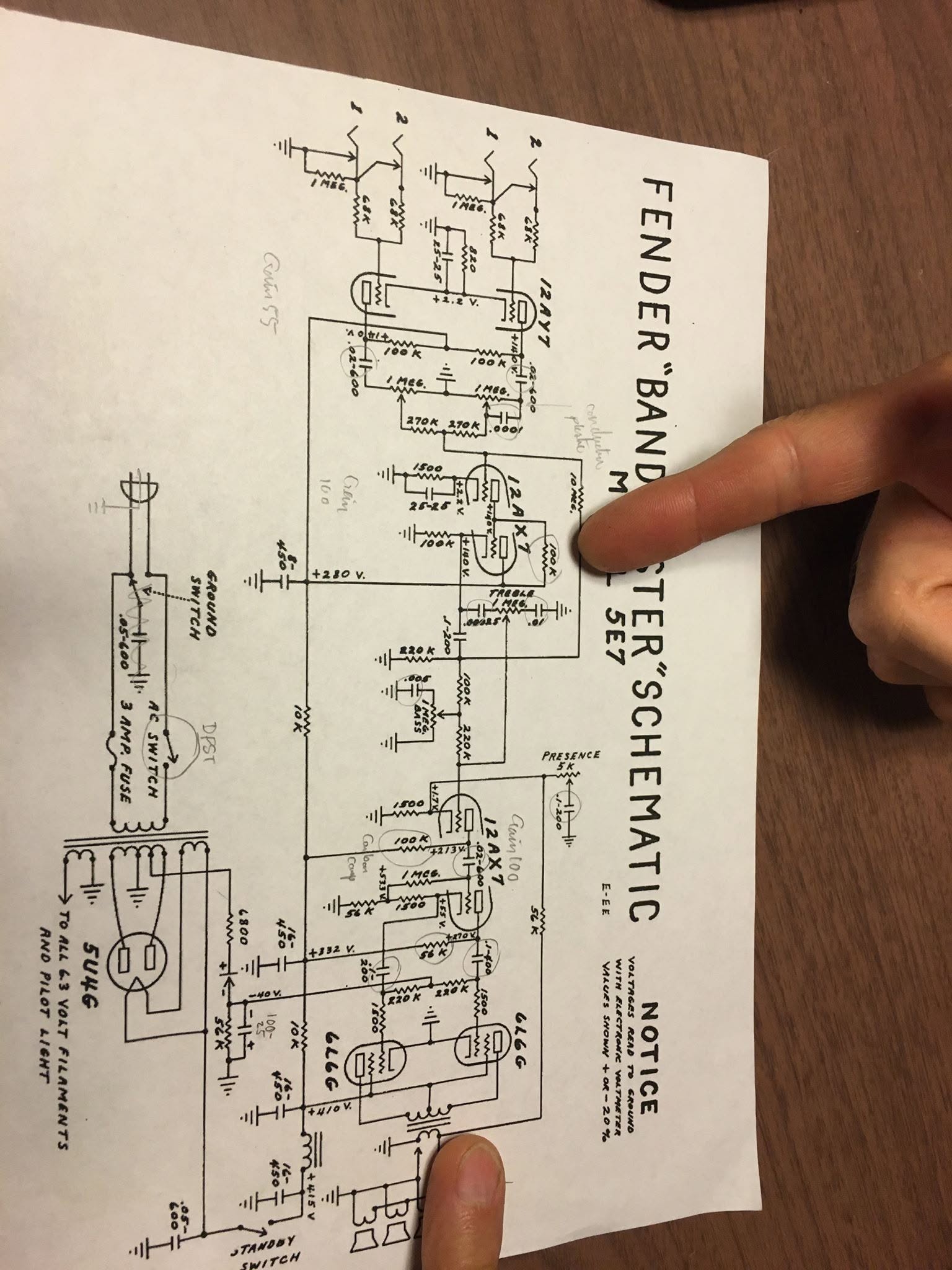
The first photo from Facebook. A fingertip covers part of the title, but enough shows through to read FENDER “BAND[M]A[ST]ER” SCHEMATIC, MODEL 5E7 — and the component values are legible almost everywhere.
Then a second frame turned up, pulled back far enough to get the whole sheet in one shot:
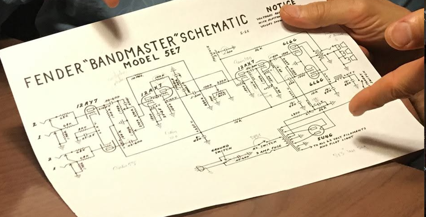
The same sheet, held up. The title is unambiguous now — FENDER “BANDMASTER” SCHEMATIC, MODEL 5E7 — along with the drawing revision code E-EE in the corner. Fingers cover the NOTICE block and part of the output section, and the wider framing costs most of the small component values, so the two photos complement each other: one gives the values, the other gives the shape.
What the Amp Is
The 5E7 is the narrow-panel tweed Fender Bandmaster, built from roughly 1955 to 1960. It sits squarely in the middle of the tweed era: two channels, a three-stage preamp, a pair of 6L6G output tubes in push-pull, and a 5U4G tube rectifier. Output is in the neighborhood of 25–30 watts. The production cabinet carried three 10-inch Jensens, wired to the output jacks drawn at the right edge of the schematic.
The tube lineup reads left to right across the drawing:
| Position | Tube | Job |
|---|---|---|
| V1 | 12AY7 | First gain stage, both channels |
| V2 | 12AX7 | Second gain stage, drives the tone stack |
| V3 | 12AX7 | Long-tail phase inverter |
| V4, V5 | 6L6G | Push-pull output pair, fixed bias |
| V6 | 5U4G | Full-wave rectifier |
The 12AY7 in the first position is the tweed signature. It has roughly a third the gain of a 12AX7, which is why these amps stay clean well past where a later blackface amp would start to break up — and why swapping in a 12AX7 is the first thing half the internet will tell you to do to one.
Signal Path, Left to Right
Inputs. Two channels, each with a pair of jacks marked 1 and 2. Each jack feeds through a 68 kΩ grid stopper; the two 68 kΩ resistors also form the classic Fender mixing and isolation network, so plugging into input 2 drops the level about 6 dB. Each channel gets its own 1 MΩ volume pot.
First stage. Both triode halves of the 12AY7 share an 820 Ω cathode resistor bypassed by a 25 µF capacitor, with 100 kΩ plate loads. The marked plate voltage is +140 V and the cathode sits around +1.2 V — a low-current, low-gain, very clean operating point.
The mixer. The two channels join through a pair of 270 kΩ resistors into the grid of the first 12AX7. This is where the amp stops having two separate channels and starts having one. It is also the point that makes the old jumper trick work: patch one channel’s input into the other channel’s second jack and you get both volume controls in series on the same signal.
Second stage and tone stack. The 12AX7 runs a 1500 Ω cathode resistor with a 25 µF bypass cap, +140 V on the plate, and feeds the tone stack directly. The stack is the Fender topology in its early form: a 100 kΩ slope resistor, a 1 MΩ TREBLE pot with small mica caps across it, and a 1 MΩ BASS pot to ground. The output runs through 100 kΩ and 220 kΩ resistors into the phase inverter grid.
This stack is famously lossy — it throws away a great deal of signal to get its shape, which is exactly why the stage in front of it is a 12AX7 rather than another 12AY7. The 5F6-A Bassman used the same arrangement two years later, and when Jim Marshall copied the Bassman for the JTM45, this tone stack went to England with it.
Phase inverter. The second 12AX7 is a long-tailed pair, splitting the signal into two opposite-polarity halves to drive the output tubes. Its cathode sits near +1.7 V.
Presence. The 5 kΩ PRESENCE pot at the top of the drawing is not a tone control in the usual sense. A 56 kΩ resistor carries negative feedback from the output transformer secondary back toward the phase inverter. The presence pot, with its capacitor to ground, shunts the high-frequency portion of that feedback away before it arrives. Less high-frequency feedback means more high-frequency gain. You are not boosting treble; you are selectively removing the amp’s own correction.
Output stage. The two 6L6G tubes get their grids through 220 kΩ resistors from a negative bias supply — this is fixed bias, not the cathode bias of the smaller tweed amps — with 1.5 kΩ screen resistors and plates on the output transformer primary. The plate node is marked in the +410 V range.
The Power Supply
The bottom third of the drawing is all power, and it is worth reading on its own.
The 5U4G rectifier feeds a filter chain of 16 µF/450 V capacitors separated by 10 kΩ dropping resistors and a choke, stepping the B+ down node by node: roughly +415 V at the reservoir, down through the screen supply, down again to the +280 V node that feeds the preamp plates. A STANDBY SWITCH sits after the choke, so the tubes can warm up with filaments lit and no high voltage on the plates.
The bias supply is the small branch with the 6800 Ω and 56 kΩ resistors and the 100 µF/25 V capacitor, producing the negative voltage (marked around −40 V) that holds the 6L6 grids below their cathodes.
And then there is the part that should make anyone restoring one of these stop and think:
GROUND SWITCH — a switch selecting which side of the AC line gets tied to the chassis through a .05 µF/600 V capacitor.
That is the “death cap.” On a two-wire amp with no safety ground, it was the era’s answer to hum. When it fails short — and they do fail — the chassis, and therefore the strings, go to line voltage. Every competent restoration of a tweed amp removes that capacitor and the ground switch and installs a modern three-conductor cord. If you own one of these, that is not an optional upgrade.
Reconciling the Two Photos
The wide shot was taken to answer the obvious objection: how much of that reading came from actually seeing the drawing, and how much came from knowing what a tweed Fender is supposed to look like?
Set side by side, the second photo confirms the whole floor plan without contradicting anything:
- The model. No more bracketed guessing. The title reads FENDER “BANDMASTER” SCHEMATIC, MODEL 5E7, with the factory drawing code E-EE beside it.
- The layout. Signal flows left to right across the upper two-thirds — input jacks, 12AY7, mixer, 12AX7, tone stack, phase inverter, 6L6G pair, output transformer — while the entire power supply runs along the bottom as a separate band. That separation is why these sheets are so readable: nothing crosses between the two halves except the B+ taps coming up from below.
- The feedback loop. In the wide view you can follow the negative feedback as one long wire running from the output transformer all the way back left along the top of the drawing to the presence pot and the 56 kΩ resistor. In the close-up it is easy to mistake that for a supply rail. It is not — it is the amp listening to its own output.
- The right edge. The choke, the standby switch, and the transformer secondary feeding two jack symbols in parallel are all confirmed, along with the last 16 µF/450 V filter cap in the chain.
- The annotations. They are scattered across the entire sheet rather than clustered in one area — preamp, tone stack, output stage, and power supply all got marked. That is a whole-amp survey, not a single repair.
What the second photo costs is detail. Pulled back and held at an angle, most of the small component values stop being readable, and the fingers have moved to cover the NOTICE block and part of the output section — exactly the regions the first photo showed clearly. So neither frame is sufficient alone. Together they are: one carries the values, the other carries the shape.
Two things stay unresolved. There is additional handwriting along the lower right edge of the sheet that neither photo renders legibly, and the marked node voltages can only be read from the close-up — which is fine, since the printed notice allows them ±20% anyway.
The Pencil Marks
The annotations are the most interesting thing in the photo, because they tell you what the person holding the paper was actually doing.
- “Gain 100,” “Gain 100,” “Gain 55” — written next to the preamp stages. Somebody was working out the voltage gain of each stage by hand. The 55 belongs to the 12AY7, the 100s to the 12AX7 stages. Those are the right ballpark numbers, and their ratio is exactly the tweed character described above.
- “carbon comp” — marking a resistor to be replaced with a carbon composition part rather than a modern metal film. An authenticity choice, and a noise-and-tone argument that has been running for forty years.
- “conductive plastic” — a note about pot construction, written into the tone stack region.
- Circled components throughout — the shopping list. The circles land on the 100 kΩ plate loads, the tone stack caps, the screen and bias resistors, and the filter caps: precisely the parts you touch in a cap job and restoration.
Put together, this is not someone reading a schematic for fun. This is someone planning a rebuild, stage by stage, deciding which parts to replace and with what.
The printed NOTICE in the corner covers the rest: voltages read to ground with electronic voltmeter, values shown + or − 20%. Twenty percent is a wide door, and it is honest about what mains voltage and sixty-year-old components will do to your measurements.
Why This Is Worth Doing
A schematic like this is a complete description of a machine on one sheet of paper, hand-lettered, readable by anyone who learned the symbols. Point a model at a photo of one — fingers, glare, folded corner and all — and it can walk the signal from the input jack to the speaker, explain why each part is the value it is, and flag the one component that could kill you.
The amp is seventy years old. The drawing still works.
References
- Schematic Heaven — Fender amp archive — original factory schematics and layouts, including the 5E7
- Rob Robinette — Tweed amp circuit analysis — stage-by-stage explanations of the 5E-series circuits
- The Tube Amp Book, Aspen Pittman — the standard printed reference for vintage Fender circuits